Internal and External Boundaries
Hydraulically, an "internal boundary" is any internal computational reach (a reach is a length between sections xi and xi+1, such as a pipe, a junction or a manhole node) for which special equations are used to replace one or both of Equations 14.1 and 14.2 normally applied to a friction-slope-dominated-dynamic reach. Although they are called internal boundaries they are still part of the St. Venant equation matrix system. These internal boundaries may include manholes, junctions, controlling structures such as gates, weirs and orifices, storage facilities such as ponds and wet-wells; or any particular reach which needs to be treated differently other than a normal dynamic reach, such as one user specifies to use culvert treatment. The external boundaries are those of most upstream and downstream boundaries in a sewer system for which a boundary condition, such as a discharge hydrograph, a tidal or stage hydrograph or an equation defining a relationship between stage and discharge is given, or simply a free outfall.
The four-point implicit scheme used in the model is very flexible in dealing with any type of internal boundaries. Because the new equations for replacing Saint-Venant equations involve only the junction reach and its corresponding elements in the matrix, the Newton iteration technique can still be used without any case-based modifications. Most commonly used alternative equations for simulating the internal boundaries are:
A storage equation, which accounts for dynamically changing storage volumes in a junction structure with inflows and outflows, is used to replace the continuity equation (Eq.14.1) for manholes, ponds and wet-wells. A general storage equation is in the form of:
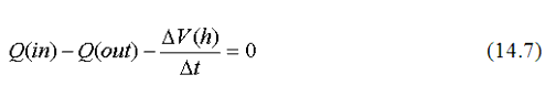
In which Q(in) and Q(out) are the flows into and out of the node and 
V is the volume change during the time step. If user specifies storage area on the ground, the equation is able to simulate the storing and draining effect duo to the manhole surcharge caused volume change. The storage areas above the ground can be represented by either user input table of areas and elevations or by model defined smooth transition function when there is no surface storage data available, which determines the areas from the junction, chamber area to about 1200 times that of the chamber area, the empirical storage equation is defined as

Sa is the ground storage area (acres) and H is the head above the ground, it also limits to the 1200 times of the manhole chamber area, Sam. User can also specify that there is no storage above the ground and in this case the manhole overflow occurs when the manhole HGL is above the ground rim elevation. The street flooding will be discussed in following section.
An energy equation is usually used in sewer manholes or junctions to replace the Momentum equation (Eq.14.2) if user specifies to add head loss calculation in the manhole. Different methods to calculate the energy loss are provided. The HGL-based energy equation is generally in the form of
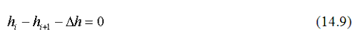
in which hi and hi+1 are HGL's in the upstream and downstream sections and ?h is the head loss calculated by appropriate loss equation. The head loss methods include:
Some hydraulic equations, such as weir flow equations and orifice flow equations are used to automatically generate necessary matrix elements for different hydraulic controlling structures such as weirs and orifices to replace the momentum equation. A user specified rating curve can also be used for any internal boundaries. The control equation is generally in the form of

Qcontl is the flow given by the control structure. For example, a rectangular flow is defined by:

Where Cw is the weir flow coefficient (typical value is 3.0 - 3.5 for U.S. customary units and 1.8 - 1.9 for SI units), the exponent e =1.5 for a inline weir and 1.67 for a side weir which divert flow from the main waterway, H is the head over the weir, L is the weir crest length. Corrections for end contractions are also considered in rectangular inline and side weirs. A V-Notch weir flow is defined by:

Where 
is the triangular weir angle, the orifice flow is defined by:
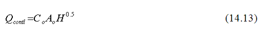
Where Ao is the area of the opening and Co is the orifice discharge coefficient and its typical value is 0.6.
Other structures are similar with using appropriate equations.
In the case of significant slope changes at a junction which results in an apparent flow regime change at the junction, such as a drop manhole, sometimes the normal flow equation or the critical flow equation, depending on the flow regime change, is used to replace the momentum equation.
The external boundaries are the most upstream end section or most downstream end section. Mathematically they are known as boundary conditions. Usually an external upstream boundary condition is a manhole node or open channel section where there may be a point inflow (either from a linked surface catchment runoff hydrograph or a user input hydrograph, patterned loads or a flow from a surface gutter). An external downstream boundary condition can be one of followings: